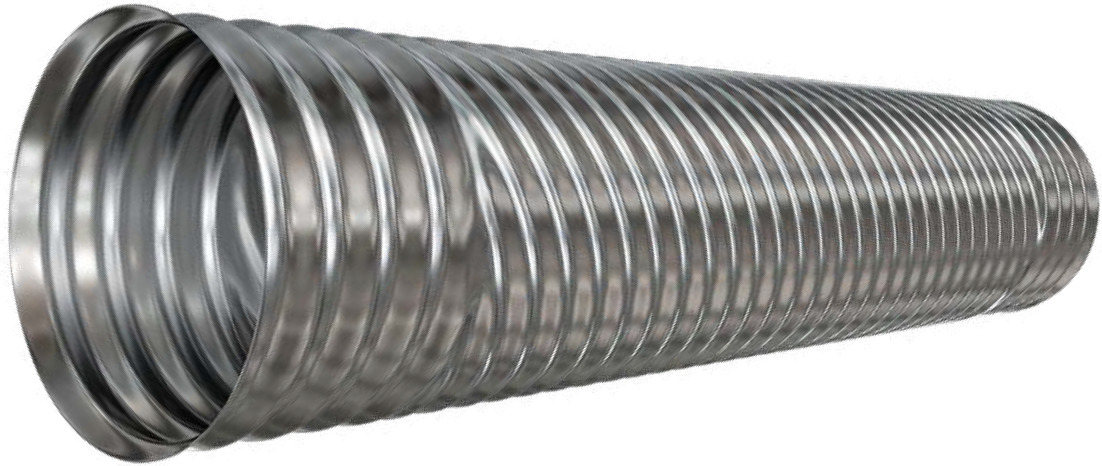
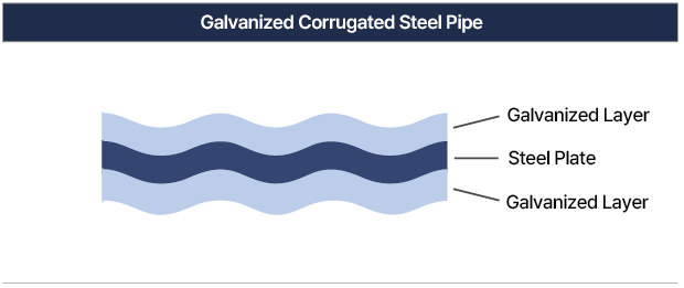
This KS-certified product is manufactured in accordance with the Korean Industrial Standard KS D 3590 for corrugated steel pipes and sections. Corrugated galvanized steel sheets are formed to increase structural stiffness and then spiralformed to create a pipe with excellent durability and structural stability. The result is an ideal drainage structure that is highly resistant to corrosion, offers a long service life, and provides superior cost-efficiency and ease of installation.
They are widely used in various civil engineering applications such as superior drainage and sewer systems for land development, road and railway cross-drainage, agricultural water channels, landfill and soft ground projects, box-culvert alternatives, golf course facilities, temporary waterways, and irrigation pipelines.
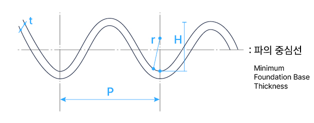
| Designation | Pitch(P) | Depth(H) | Bend Radius(r) | Pipe Length(L) | Nominal Diameter(RI) |
Axial Bending |
|---|---|---|---|---|---|---|
| 0RS | 38.0 ± 2.0 | 6.5 ± 2.0 | - | +40 -10 from specified length |
10 for < 1000 / ±1% for ≥1000 |
±0.3% of length |
| 1RS | 68.0 ± 2.0 | 13.0 ± 2.0 | 17.5 | |||
| 3RS | 76.2 ± 2.0 | 25.4 ± 2.0 | 17.5 |
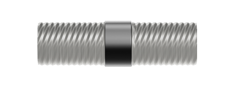
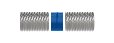
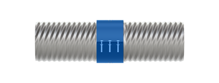
The most commonly used coupling method, in which a watertight gasket is attached to the outer surface of the reformed pipe ends and secured with a coupling band fastened by bolts.
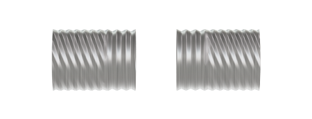
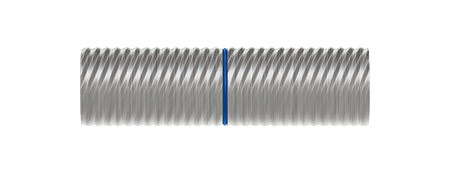
A connecting device for corrugated steel pipes with small nominal diameters such as
0RS and 0RS perforated pipes, where a
sleeve is inserted into the inner diameter of the untreated pipe ends and the outer circumference
is sealed with waterproof tape.
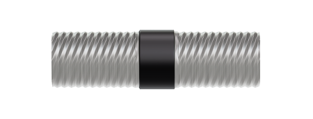
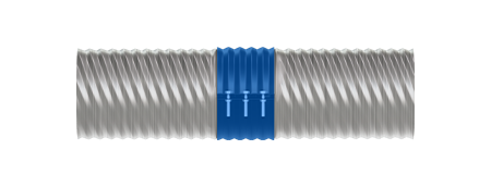
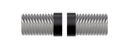
A flange-type coupling device primarily used in environments requiring high
watertight performance. The pipe ends are sealed with a
watertight sheet on the outer surface and secured using a flange band fastened with bolts.

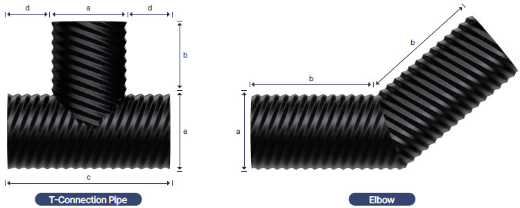
| Designation | Branch Pipe Diameter(a) | Main Pipe Length(c) | Branch Pipe Length(b) | Width(d) |
|---|---|---|---|---|
| a | a + 2d | c ÷ 2 | 250 |
| T-Connection Pipe (Reducing T-Connection Pipe) |
Diameter difference between main and branch pipe ≤ 500 mm (e - a ≤ 500 mm) | ||||
|---|---|---|---|---|---|
| Branch Pipe Diameter(a) |
Main Pipe Length(c) |
Branch Pipe Length(b) | Width(d) | ||
| Branch Pipe Diameter ≤ Ø1,000 |
Branch Pipe Diameter > Ø1,000 |
||||
| a | a + 2d | c ÷ 2 | a ÷ 2 | 250 | |
| Diameter difference between main and branch pipe > 500 mm (e - a > 500 mm) | |||||
| Branch Pipe Diameter(a) |
Main Pipe Length(c) |
Branch Pipe Length(b) | |||
| Branch Pipe Diameter ≤ Ø1,000 |
Branch Pipe Diameter > Ø1,000 |
||||
| a | e | 500 | c ÷ 2 | ||
| Elbow | Angle | Pipe Diameter(a) | Width b |
|---|---|---|---|
| 45° or 90° | a | 250 |
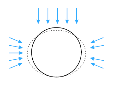
Corrugated steel pipes excel in both cost-effectiveness and constructability, but quality control throughout the construction process is crucial. Unlike other structures, underground corrugated steel pipe structures require thorough preparation and inspection for quality management at every stage of construction. The support mechanism of a corrugated steel pipe is illustrated in the figure. When the pipe deforms to some extent under external loads, passive earth pressure develops on the sides in response to this displacement, thereby supporting the structure. Therefore, the selection of suitable backfill materials and proper compaction—particularly in the haunch area—is of utmost importance. Excavation
Excavation shall be carried out in compliance with the standards specified in the Road Construction Standard Specifications. When installing corrugated steel pipes in ordinary ground or compacted soil, it is ideal to minimize the excavation width and maintain vertical sidewalls for optimal construction quality.
| 관경 | 300 | 400 | 500 | 700 | 900 | 1100 | 1300 | 1500 |
|---|---|---|---|---|---|---|---|---|
| Excavation Width | 700 | 900 | 1100 | 1400 | 1700 | 2000 | 2200 | 2500 |
| 관경 | 350 | 450 | 600 | 800 | 1000 | 1200 | 1400 | - |
| Excavation Width | 800 | 1000 | 1200 | 1600 | 1800 | 2100 | 2400 | - |
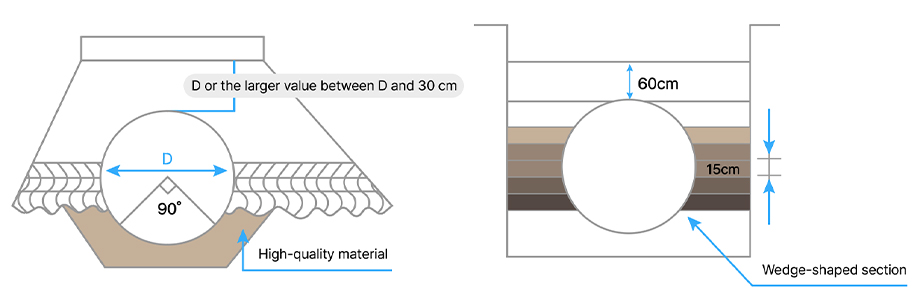
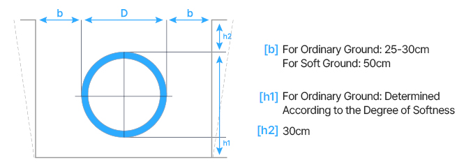
Since corrugated steel pipes are flexible structures, a foundation capable of evenly distributing loads is required. Therefore, it is recommended to use high-quality materials such as sand or sandy soil for the foundation and to compact it uniformly according to the ground conditions.
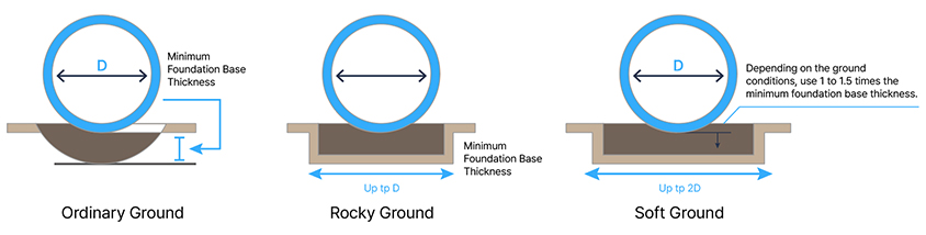
| Foundation Soil and Pipe Diameter / Thickness / Width | Minimum Foundation Thickness(H) | Foundation Width(W) | ||
|---|---|---|---|---|
| Up to 900mm | 900 ~ 2,000mm | 2,000mm or more | ||
| Ordinary Ground | 20cm | 30cm | 0.2D | D |
| Rocky Ground | 20cm | If the embankment height exceeds 5 m, increase by 40 mm for each additional meter |
D | - |
| Soft Ground | 50cm | The greater value of 0.4D / 500mm |
0.3D (Up to 1m) | 2D ~ 3D |
| Clay | Silt | Sand | Gravel | Stone | ||||
|---|---|---|---|---|---|---|---|---|
| Fine-grained | Medium-grained | Coarse-grained | Fine-grained | Medium-grained | Coarse-grained | |||
| 0.002 | 0.006 | 0.02 | 0.06 | 0.2 | 0.6 | 2.0 | - | - |
Installation of corrugated steel pipes shall be carried out according to the dimensions indicated in the design drawings and at the slope specified in the drawings or as directed by the supervisor. When installed within embankments where significant future settlement is anticipated, the design shall include a height allowance for the estimated settlement in accordance with the design drawings or the supervisor’s instructions.
Installation of corrugated steel pipes shall be performed using pipes of the dimensions specified in the design drawings and at the slope indicated in the drawings or as directed by the supervisor. When installation is carried out within an embankment where significant future settlement is expected, the design shall include an allowance for the estimated settlement height in accordance with the design drawings or the supervisor’s instructions.
The minimum height of the embankment shall be the greater value between 30 cm above the pavement surface or D/5. It is recommended to use the same material for the embankment as that used for backfilling.